|
Properties: No SMD. |
 |
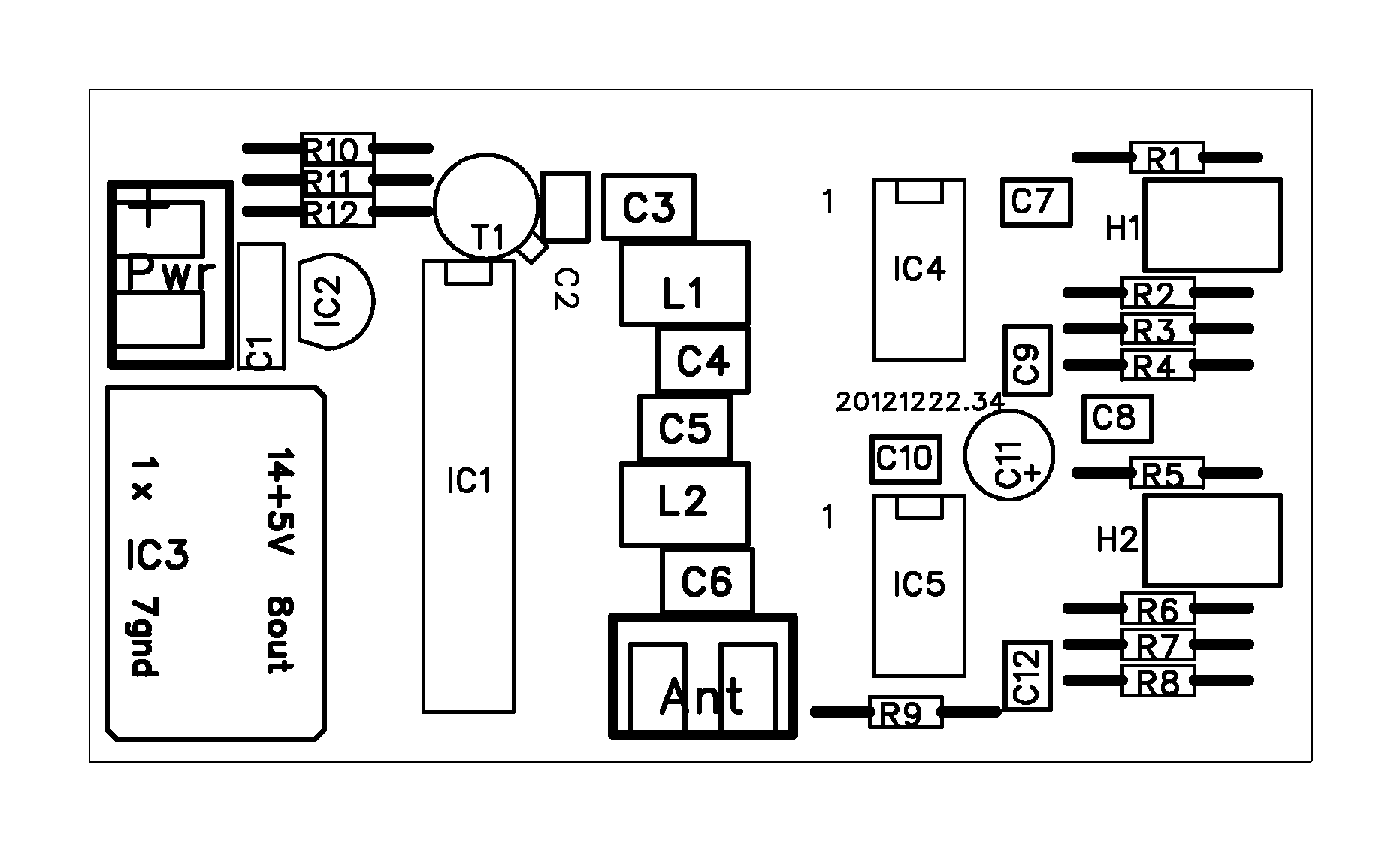
Small, simple, low power, modulated 3,579545MHz foxoring transmitter.
pa0nhc, 20121224 v8-34. 20150123 layout.
Warning:
This design is ultra simple, after an idea of the ARRL. It is meant as a milliwatt, very limited range foxhunt transmitter, connected to a low efficiency
antenna system.
>>> Modulation is simply done by switching on/off the ports of the 74HC240 <<< .
The drawback of this simplicity is: WIDE modulation bandwidth.
>>> DO NOT use this little transmitter as a driver stage for a power amplifier <<<
Use this double sided PCB design. Do not use the schematic to build it on a single sided PCB. The chance is great that digital and RF path do cross each other. On a small single sided PCB, you will inject digital spikes from the oscillator unit and/or the tone oscillators into the antenna.
|
Properties: No SMD. |
|
Construction hints: A number of pads serve as "via".
In home made PCBs those "via"-pads do not contain conducting bushes, while factory made PCBs do.
In home made PCBs you must therefore, where possible, solder all connections on BOTH sides of the PCB. Solder connections on the TOP copper surface
FIRST.
TIPS: Some components must be lifted 1 or 2mm from the top surface, in order to be able to solder them at the top copper surface. Place IC2 (7805) AFTER soldering C1 and IC1 (74HC240). Do not use an ICsocket for IC1. Solder IC1 directly into the PC.