|
|
| << |
The ferrite antenna. |
(Copyright) The use, copy and modification of all info on this site is only permitted for non-commercial purposes and thereby explicitly mentioning my radio amateur call sign "PA0NHC" as the original writer / designer / photographer /publisher.
|
|
Ferrite antenna rods :
Long Wave broadcast receiving antenna ferrite rods are NOT suited for use above 300 kHz.
For
SW bands, especially suited are ferrite rods fro material #61 with Ui=125.
Amidon or Fairrite R61-050-400 (100mm long)
or R61-050-750 (190mm long).
But they are very expensive.
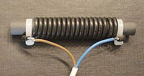
For 20 uH and 80m band use, wind 18 to 22 turns insulated thick wire over a length of
abt. 72mm on a Amidon R61-050-400
ferrite rod.
These ferrite type 61 rods can be used from VLF up to 21MHz, and are available at
:
"amidon.de"
and "alltronics" and on
eBay.
Very
cheap and short length, but successfully used in 80m
RDF receivers : 50x8mm Ui=300 :
Conrad orderNrr 1565952
|
|
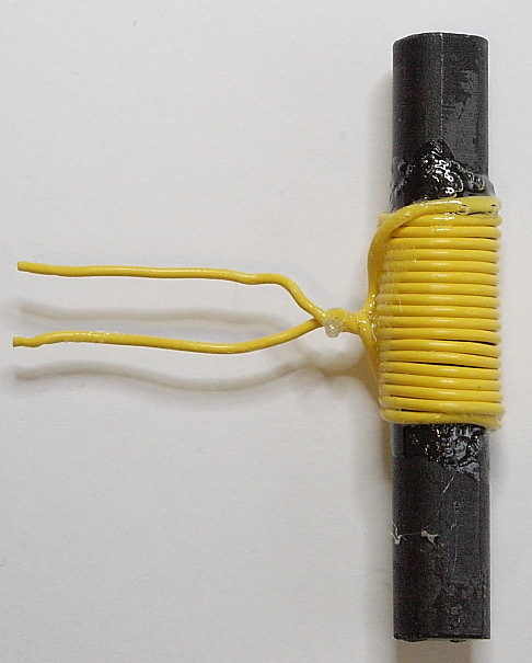
Wind closely 18 turns insulated 0.8mm wire for 20 uH.
Due to their higher Ui than #61 material, their upper frequency range is
limited.
A long but relative cheap rod with Ui=250 is available at BOX73.DE. BestellNr : FS-200x10
For the 80m band and a tuning range of 300 kHz, pre-adjust the coils self inductance to 20 uH
as follows :
Temporarily solder a test capacitor 100pF 1% directly onto the connections of L1. This test combination should resonate at 3.50 MHz. Check it using a
GDO. Or measure the self inductance using an inductance meter.
Start with one or two turns to much, and remove one turn until the resonance frequency is nearly correct.
You can fine-adjust the coils self inductance, by adjusting the separations between all windings equally (the total coil length will change too). All windings should have equal separations.
Once finished, fix the coil windings and ends with glue (i used successfully : Bison Kit Transparent Water Resist).
Remove the 100pF test capacitor.
 |
Connect a rather long pair twisted wires.
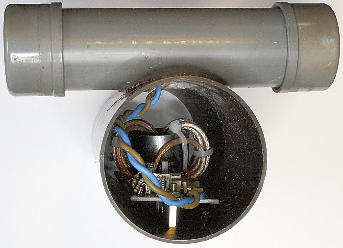
The long ferrite rod antenna coil fits inside a 32mm PVC pipe.
- First put the connecting wires in this 32mm pipe, through a small hole in
the center of it, and then into the 50mm main
housing pipe.
- Put soft plastic foam over the ends of the ferrite rod. It must guard the rod against
shock, strain and breaking.
- While pulling back the connecting wires, shift the ferrite rod into its 32mm pipe.
- Close the 32mm antenna coil PVC pipe water tight with end caps.
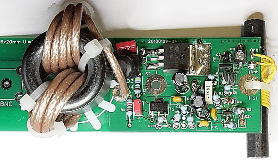
You must be able to adjust C11 on
the antenna PCB.
- Before connecting the antenna coil to the
PCB, shorten the antenna coil wires just long enough, to be able to lift the antenna PCB
out from, and put it back into the tube.
The short 50x8mm ferrite antenna rod
could be mounted on the top of the antenna
PCB, using a plastic strap through the PCBs top screw hole.
Place the PCB+50mm rod into a 60mm PVC pipe. You could fix the PCB in the pipe
by means of a screw and mounting stud in the bottom PCB hole.
Grounding.
The metal mounting posts used to screw the PCB into the plastic tube, are
connected to the ground surfaces of the antenna PCB.
You could connect a grounding wire to it, inside the tube, our outside.
This wire should be connected to a noise free grounded antenna pole.
WARNING : withpout proper grounding of the antenna PCB, mantle current choke L6
CANNOT block noises which will be induced onto the
connecting coax cable.
This
antenna performs as good as its noise free grounding and its noise free
installation location is.
Installing without proper grounding is useless.
|
|
|
|
This results in a very unsuspicious antenna. Just ONE piece of vertical gray PVC pipe. Still sensitive, and if rotate able, capable of suppressing nearby noise sources. 80m band RDF receivers prove it.
A coil for other frequency bands.
A type #61 ferrite rod can be used up to 21MHz. When used outside the 80m
band, L1 must get another value of self inductance, hence number of turns.
For instance 13 turns or 9 turns for 7MHz or 14MHz. Divide
all turns equally over abt. 70mm rod length.
The shorter 50mm Ui=300 rod could also be used for lower frequencies than 3.5 MHz, with more turns of thinner wire.
For frequencies below 1.6 MHz use
surplus MW or LW receiving rods. with their original coils.
You also have to adapt the capacitance values of C12 and C12a.