 |
| Fig.1. |
 |
| Fig.2. |
 |
| Foto 1. |
 |
| Foto 2. |
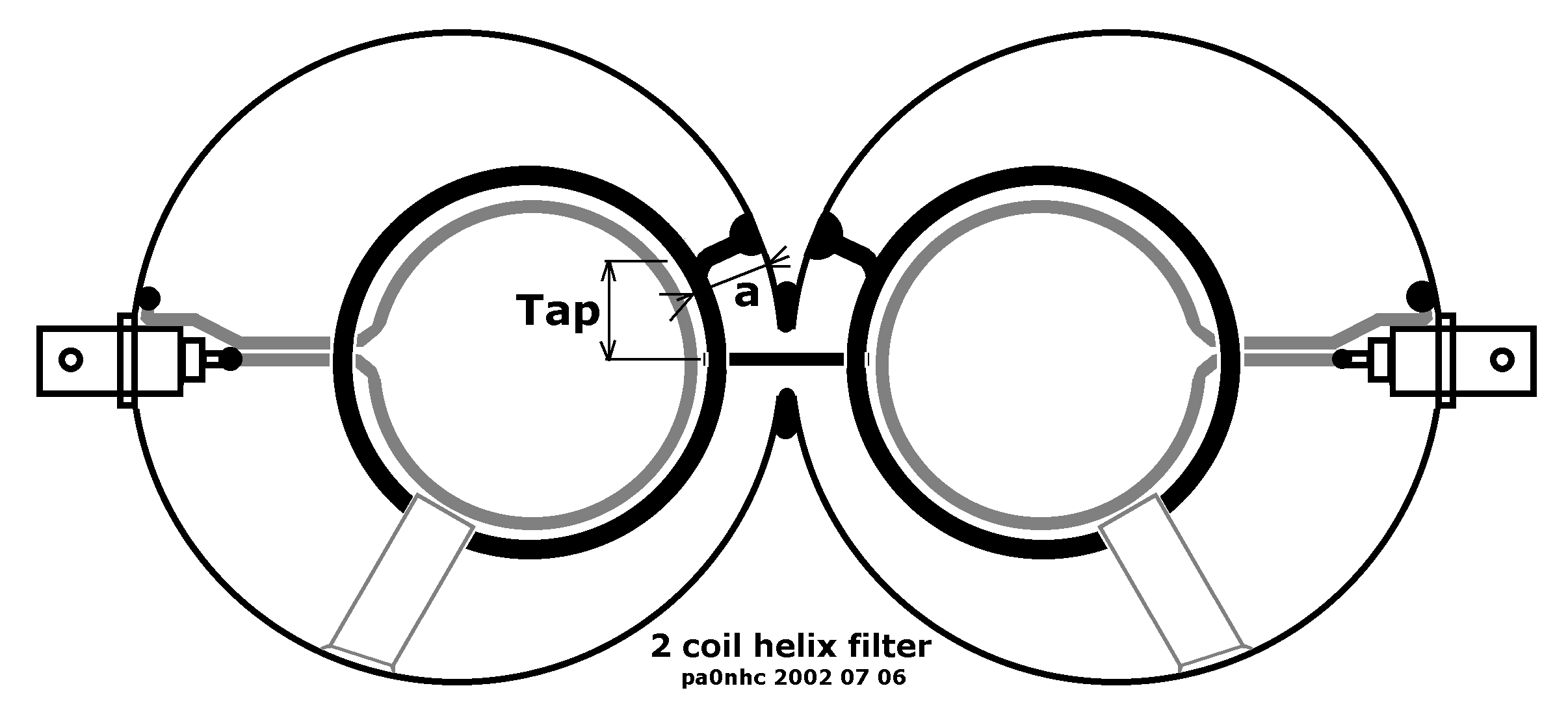 |
| Fig. 3. |
| A two resonator helix band pass filter for the two meter band. pa0nhc, 2002 07 07. / 20110307. |
|
| Fig.1. |
|
| Fig.2. |
|
| Foto 1. |
|
| Foto 2. |
|
| Fig. 3. |
Elsewhere on this site you can find a description for the construction of a single helix band pass filter.
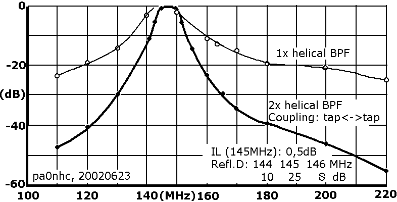
Two of those, identical filters, were coupled using BNC-male-male connector between the "Tap" ports (see fig.3). On the "Link" ports the frequency characteristic of fig. 1 was measured.
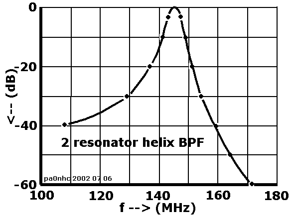
Below, you can find the building description of a double tuned helix band pass filter, from which the two screenings are combined into one housing. The interconnection between the resonators now is as short as possible, and the filter can be adjusted as a whole. Two of these filters were made. The measured results showed to be nearly identical, proving the design is reproducible. In fig. 2 the frequency characteristics of this filter is shown. Insertion loss was 0.7 dB, 1-dB-bandwidth was 2.6 MHz.
Eye catching is the difference in attenuation around 160 MHz. It is about 15 dB better than in the combination of two separate resonators. Broadcast signals around 100 MHz will still be suppressed at least 40 dB (100x).
|
||||||||||||||
| Table 1. |
By connecting two of these filters in series with a 1/4 lambda cable, superior selectivity is obtained.
See "A four helix resonator band pass filter".
Construction.
The construction of a resonator is similar to the elsewhere on this site described construction of a single band pass helix filter. Read this article for more info. However, the
dimensions differ. See fig. 3 and table 1.
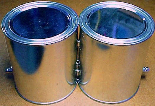
| - | Drill in two new, clean paint cans of 3/4 liters, dia. x height = 100 x 115 mm, the 9.5 mm dia holes for the BNC and inter connection holes. |
| - | Put both cans on a flat surface against each other, with the BNC- holes in 1 line. |
| - | Solder the upper rims of the cans together, using a hot solder iron of at least 50W. |
| - | Turn the cans top down. Solder the rims on the bottom together. |
| - | Flow solder between the cans around the interconnection holes, so the holes will be screened and interconnected the shortest way possible. |
| - | Solder both BNC-receptacles. |
| - | Wind both helix coils (4 turns tinned copper wire, 3mm dia. = 6 mm2). Left and right pitch at choice. Check that the winding pitch is even. Mark, using a felt pen, on both coils the places where the "Taps" must come. |
| - | Bend the mass connections at 90 degr, and cut them. The length is critical! |
| - | Make the two coupling links. Use insulated copper wire, 1.7 mm dia = 2.5 mm2. Twist the connection wires. Strip the isolation for the connections. Bend the mass-connection in shape. Cut excess wire. |
| - | Put temporarily on botch BNC receptacles a plug, to center the bushing during soldering, and cool the insulation. |
| - | Tin all places to be soldered on the BNC's, links, coils and screening. |
| - | Solder de helix coils in place. The helix coils must be placed with the "Tap" markings on the helix coils exactly at the centerline of the interconnection hole. This makes correcting the coupling easier later on. |
| - | Place the interconnection wire in the interconnection hole, and solder the wire on the "Taps" of the helix coils. |
| - | Solder the coupling links in place, under the helix coils. Between the link and the helix coil should be 3 mm free space. Keep this space equal in both cans, and the link and helix coil concentric. This is critical. |
Tuning of helix coils.
Both helix coils interact, as they are coupled by the links. If one of the coils have to be measured, the other one has temporarily to be
detuned or "damped". This is easiest done, by "shortening" the helix to the screening by hand, while measuring the other helix. Little signal then is coming
through the filter, so a strong signal from the generator is needed, together with a sensitive measuring receiver.
| - | Connect on one port a signal generator, on the other a measuring receiver. |
| - |
Damp one coil. Measure the resonance frequency of the other, by finding the peak in filter output. Fine tuning is done, by bending the last 2 cm of the coil tip. |
| - |
Repeat this with the other coil. |
Matching.
| - | Terminate one port with a dummy load (50 ohms). Measure the match of the other port, return loss should be better than 20 dB, or SWR better than 1:1.1 . Correction must be done, by changing the free space between the link coil and the helix coil. Keep it the same in both cans. Do not shift or rotate the links. |
| - | Change termination and measuring instruments to the other ports. Repeat measurements and correction. |
| - | Repeat both, until both ports show equal and over 20 dB return loss. |
| - | Measure the insertion loss on 145.0 MHz. It should be less than 1 dB. If the insertion loss is to high, the coupling by the "Taps" is to loose. Then shift the interconnection wire symmetrically so, that the "Taps' become just a bit longer. This is critical. Repeat above until reflection damping and return loss are OK. |
| - | Measure the -30 dB frequencies. They must fit with those in fig. 2. If selectivity is insufficient, the coupling by the "Taps" is to tight. Then shift the interconnection wire symmetrically so, that the "Taps' become just a bit shorter. This is critical. |
| - | If necessary, repeat until tuning, match, insertion loss and selectivity meet the demands. |
Mechanical reinforcements.
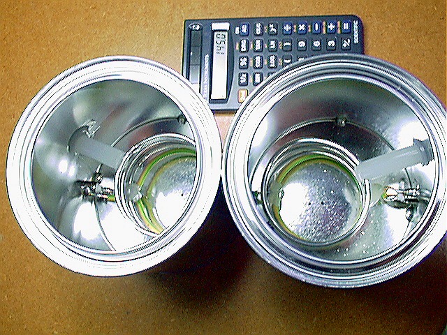
Fixate the coupling links to the helix coils, by gluing them on two places. Use a themal glue pistol. See foto 1.
Fixate also the interconnection wire to the screening.
Fixate the helix coils as follows to the screening, using a insulated support made of a thermal glue cartridge (see foto 1 and fig. 3).
| - |
Measure the free space between the helix and the screen (about 31 mm). |
| - |
Using a hot knife, cut a piece of thermal glue, 5 mm longer than measured. |
| - | Hold the support in place between helix and screen. Using a small blowtorch, carefully heathen the outside of the can near the support, until the
glue melts. Hold the support still, until cooled down completely. |
| - | Using a hot solder iron, heathen the helix just beside the place of the support, until the helix has molten itself into the support. Let it cool down. The helix now is supported without mechanical strain. |
Final check.
Due to the last mechanical changes, the tuning is probably shifted down a bit.
| - | Again, with the lids on, check: tuning, match, insertion loss, selectivity. |
| - | Note the measured results on the filter. |
73's, Nico, pa0nhc.