 |
 |
| << |
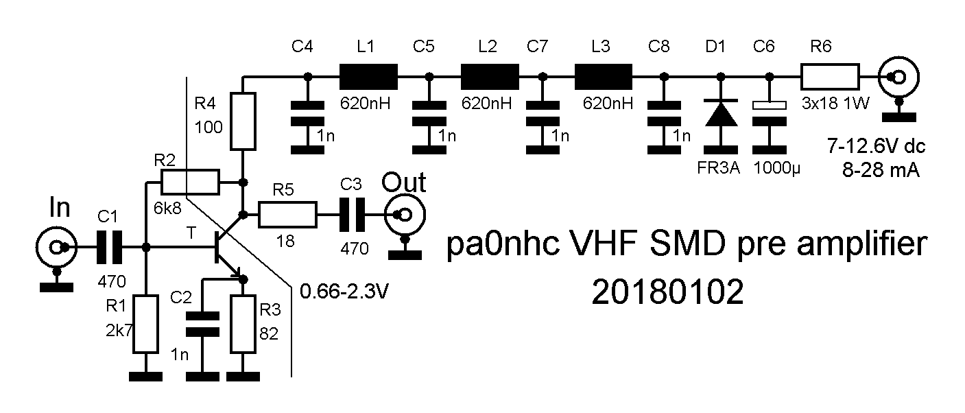
pa0nhc low noise wide band
VHF pre amplifier. |
(C)
The use, copy and modification of all info on this site is only permitted for non-commercial
purposes,
and thereby explicitly mentioning my radio amateur call sign "PA0NHC"
as the original writer / designer / photographer /publisher.
|
|
 |
 |
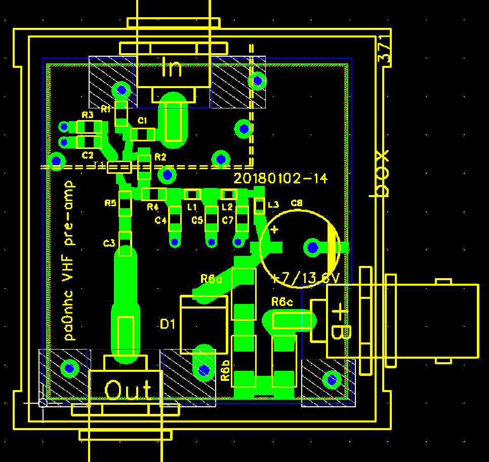
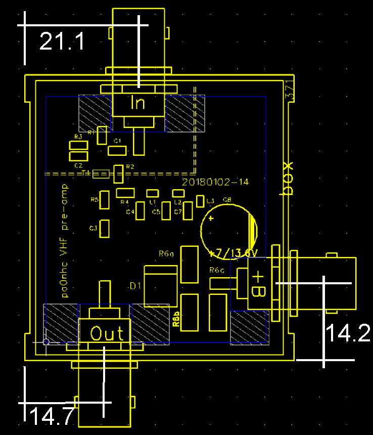
This little 41 x 46 mm PCB is DOUBLE
sided. It fist in a TEKO 371 50x53x26mm box.
The bottom copper is FULL copper and serves as return for in-out, and power.
At strategic places the bottom copper is inter connected to the mass planes at
the top copper, using "via's" with relative wide holes, for low
inductance inter connections.
Electronic parts must be soldered on the top
copper.
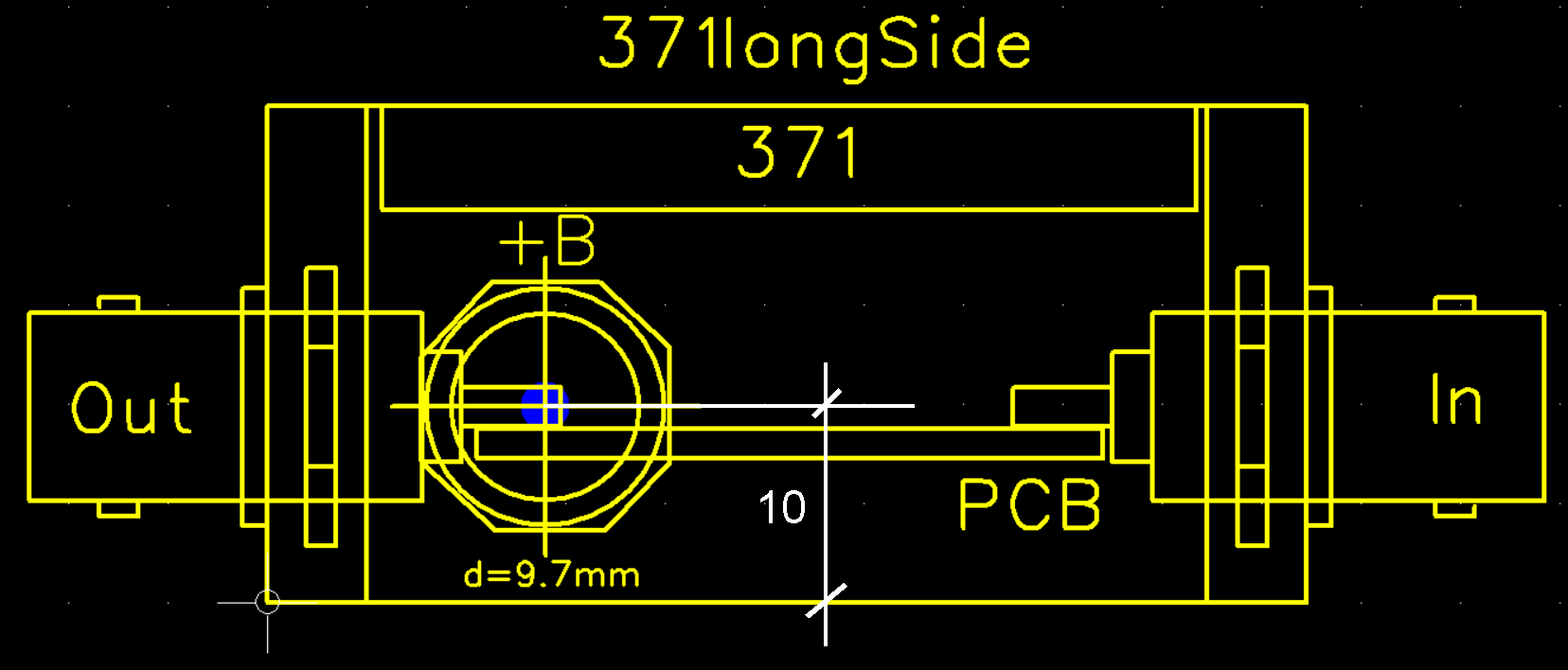
The PCB is soldered to the underside of the BNC pins.
This is a modernized version of the one with DIY PCB. The BFR91 is replaced by a BFR93, C6, R6, L1-3 and D1 are replaced by SMD types. Although N-busses with PTFE insulators could be used for repeater use, short BNC busses with nuts and "Delrin (R)" insulators are cheaper and easier to install, and satisfying for the home station
The dashed lines on the PCB top surface represent a screen, made of tinned steel sheet, copper sheet or brass sheet. In the five 1.25 mm wide "vias" can 1mm thick pieces of tinnes copper wire be soldered. The screen is placed against them, and soldered to them. It should run over the center of R2 and T1. On this place, just enough space must be made in the screen, so elsewhere the screen fits flush to the PCB. It may only make contact to the PCB surface.
- Place the PCB first before
installing the busses.
- Solder the rims of the (PTFE) BNC busses at the outside to the box.
- The PCB is soldered into the UNDERside of the BNC (N) pins.
- Solder the blank tinned PCB surfaces directly to the mass sides of the BNC
busses.
If BNC busses wth nuts will be
installed :
- place the PCB first before installing the busses.
- remove some material from the PCB to make room for the nuts.
- install ("Deltin (R)) BNCs with each two ground lugs.
- place a BNC plug on the to be soldered BNC bus or centering and cooling
- Solder the PCB into the UNDER side of the BNC pins.
- Solder the ground lugs to the blank tinned PCB areas.
-