|
|
|
| << |
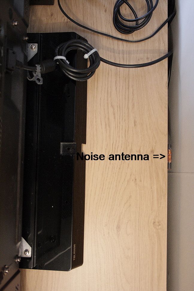
Little active noise sampling antenna. |
This little active "Noise antenna" is
as experiment developed to suppress on 80m and 40m bands the rattle noises from
my nearby plasma TV.
Placed near the TV.
For use with horizontally wire main antennas, i
suggest a vertically positioned MINIWHIP as noise antenna.
This noise antenna is tested together with my "3m circumference tuned transmitting loop". The bandwidth of the loop on 80m is only 15kHz. Tuning the noise filter was therefore critical. On 40m the loop bandwidth is 200kHz. Filter tuning is there far less critical.
Buffered active noise antenna.
If a directly to a coax cable connected small un-buffered whip antenna should be
used as noise antenna, it will only supply very-very small signal levels.
Cause : the cable capacity shortens the signals.
If a directly to a coax cable
connected ferrite antenna is
used, the cable capacitance detunes the high-Q coil to a very low frequency.
The high Q of such a ferrite coil then attenuates the signals on the wanted frequencies.
Low
noise signal levels lead to a severe drawback :
When the noise antenna delivers to small noise signal strengths, P1 in the filter unit has to
attenuate the wanted signal from the main antenna
to be weak enough to be able to cancle the to weak noise signal.
|
This little active magnetic antenna generates a relative
strong noise sample, possibly stronger than the noise level
from the main antenna. Conclusion : try to get STRONG noise signals from the noise antenna. |
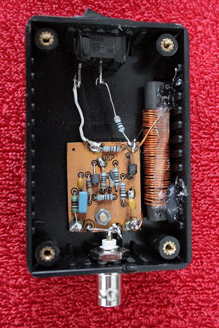
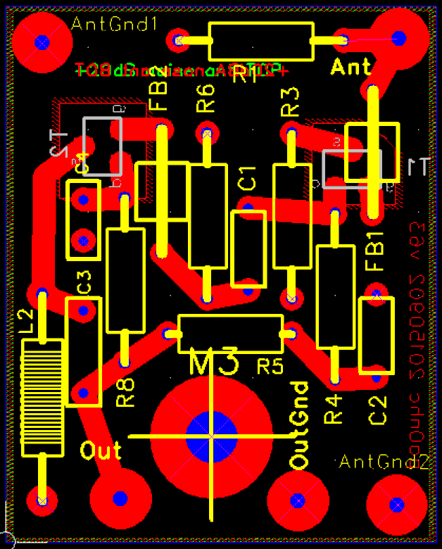
This circuit is electronically not critical. It also can be constructed as "dead bugs" on a piece of copper clad.
But keep the wiring short.
DePCB fits in a small plastic box (Hammond 1591MBK).
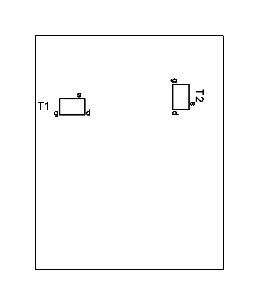
Fets T1 and T2 are soldered onto the underside. All other components on top. Glue the ferrite
antenna into a corner of the box with thermal glue.
"M3" is a 3.2mm screw hole.
If you use a horizontal wire main antenna, i suggest to test this ferrite antenna turned in exact vertical position.
|
|
|
Connect this little antenna to the filter unit using
thin 50Ohms coax
(RG174 / RG316).
DO NOT FORGET to put a MIX#31 ferrite clamp at the beginning, the end and in-between
at this coax with as much turns coax through the ferrite core as possible.
My advise : also put such ferrite clamps near the TV over all to TV, radio and amplifier connected cables there.
Placement : I had good results with this noise antenna taped at the center of the back of the TV, with the ferrite antenna in vertical position.
| X-ant TOP copper 1200DPI |
X-ant Bottom copper 1200DPI |
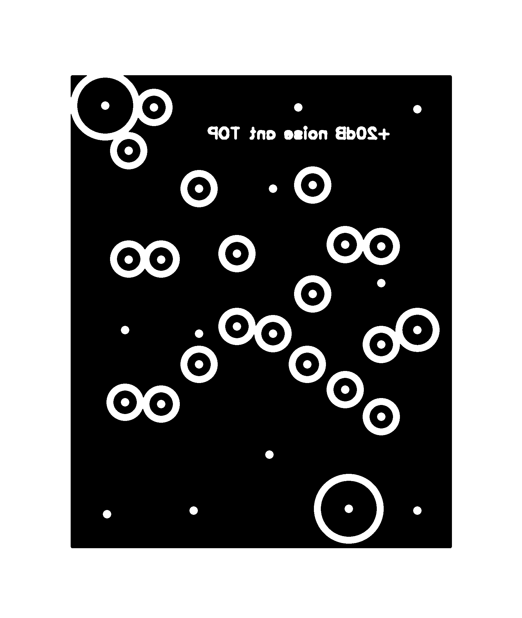
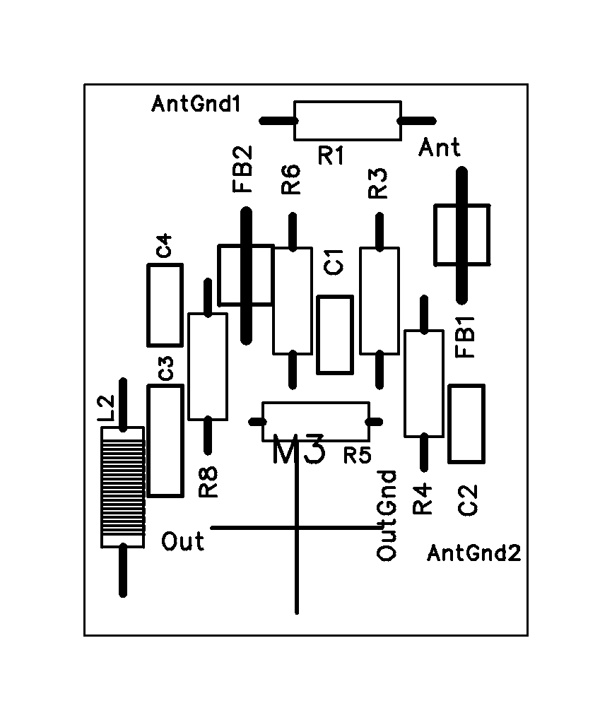
X-ant Top+parts |
X-ant XRAY |
X-ant SMD pos. |
Xant schematic 600DPI |

How this simple noise
antenna works.
This circuit is powered from the noise filter unit. In the local noise filter unit, L2/C18/TR1 combine the supply voltage to the noise antenna with the noise signals coming
from the noise antenna.
L1 is not loaded by the coax cable, and now resonates halfway the used frequency range. It is damped by R1 so the output voltage is fairly constant over the 80m and 40m bands. L1 is 50 turns 0.7mm over a cheap small ferrite antenna rod 8mm x 50mm met Ui=300 (Conrad orderNr 535575).
T1 / 2 are also the modern BF999 mosFETs, chosen for high steepness (20mS) at low drain current (10mA) and 0 gate-source voltage. The output impedance of T2 therefore is (Z=1/S) 50 Ohms, nicely matching the output cable impedance. Phase transformer Tr1 in the filter unit now sees en neat resistive source, resulting in easy adjustments of P2/3.
IMD in the noise antenna circuit will be heard in the connected receiver. R3 introduces strong feedback in T1, reducing chances of IMD. As Rs(T1) : Zd(T1) = ca. 1:10, T1 amplifies 20dB (10x). T1 only draws 3mA, the total current drawn is only 10mA.
FB1 and FB2 are 3x3.5mm ferrite beads. They suppress parasitic oscillations, and keep the antennas self noise level low. "Stop" resistors here made the self noise level higher. R8 not only is a RFfilter, but lowers the drain voltage of T2 to a safe level. C4 HAS to be a foil capacitor in order to prevent IMD (because most ceramic capacitors do make IMD).
The influence of cable lengths.
Phase adjuster P3 also can compensate for differences in cable lengths from both antennas.
If P3 is in one end-position, try :
- turning the noise antenna box by 180 degr.
- make the noise antenna cable a few meters longer.