|
|
If a network analyser is avalable, filter adjustment is easy. But it can be done using simple HAM-equipment like a home made power attennuator (roll RG58), milliwattmeter and dummyload. Or even with the use of a signal generator and a receiver. On site, insertionloss and notchdeepnes can be checked using two battery-operated handhelds, power meter, and home made switchable atennuators.
Be carefull: especially when measuring completed duplexfilters, use double screened cable and first class connectors. Eventually put ferriteclamps over cables to prevent creeping HF on the outside. HF leakage easely can couse measuring errors when looking at levels of -100dB, and make correct finetuning impossible!
|
|
With this setup, for modes 2, 3 and 4 the couplinglink can be adjusted (See fig.7). A wideband indicator is used. The Tx therefor HAS to have a clean output spectrum, with very little second harmonic content.
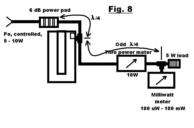
If a complete section of a duplexfilter is measured, the notchdeepnes easely can be less than the level of the second harmonic of the transmitter. You then are not measuring the notch deepness of the filtersection, but the second harmonic level of the transmitter. If between the TX and the 6dB pad an extra bandpass cavity is placed, the second harmonic is supperessed, and the 3rd harmonic is notched out, as the cavity is 3/4 lambda resonator for that frequency.
Measuring insertion loss, notchdeepness, and frequency difference:
| a. |
Disconnect the cavity under test. |
| b. | Connect the cavity under test. Tune Tx to the pass-frequency. Tune the cavity for max. output = P2. Insertionloss = 10 log10 P2/P1 [dB] |
| c. |
Tune Tx for minimum output = P3 (notchfrequency). Check for correct notch-frequency. |
Another method is:
Replace the transmitter by a signal generator, and the powermeter by a handheld receiver (portophone) on battery operation. The signal generator must be able to deliver
+100dB-microvolt. The receiver must give a good readable indication on -10dB-microvolt.
Adjust the transmitter of the portophone so, it cannot transmit (you otherwise blowup the atennuator and/or the calibrated output detector in the signal generator). Beware: if the 5 tone squelch is switched on, your transmitter will answer a 5-tone-call. Bye bye signal generator!
Check that NO signal creeps around the filter under test. So, the signal generator MUST be screened and filtered very well. The portophone must not receive anything when the signal generator output is turned to zero, or the antenna cable is removed from the receiver. By operating the portophone on battery, no signal can reach the receiver through the mains through and the power supply. If neccasery, put ferriteclamps over all cables.
In every measurement, allways readjust the calibrated output attennuator for exactly the same indication on the signal strenth indicator of the receiver. The filter insertionloss or notchdeepness (in dB) can directly be read from the difference in atennuation at the signal generator.
The correct generator frequency can be concluded from the tuning frequency of the christal-controlled portophone. So an old surplus signal generator and portophone are usable. Cheap, simple and easy.
If the signal genertor is not making enough output power for measurement of a complete filter, then use a second battery-operated portophone on low power as a high power signal generator instead, together with a 20dB powerpad, and a home made switchable atennuator. Connect the transmitting handheld to the filter via longer piece of cable, with the 20dB powerpad directly onto the filter. Keep the transmitter and the cable at some distance from the rest. Put the step attenuator between the filter and the receiver directly onto the filter.
On site, the notchdeepness of the duplexfilter of PI3RTD was sucessfully checked and corrected that way.