|
|
In practice, unexpected problems uccurred. The main problem was a limit in suppression of sidebandnoise, even when inserting extra notches on the receiver frequency.
The couse was intermodulation between the second trnsmitter harmonic and the noise energy in the non-suppressed sideband. This can occur in te circulator or in the receiver input stages.
Calculation for a 70cm repeater on RB0 (Rx freq. 434.6 MHz, Tx freq. 433.0 MHz).
| Ft | 2x Ft | Fs (Ft-Fr) | Tx lower sideband |
| 433.0 | 866.0 | 1.6 | Ft-1.6=431.4 |
| 2Ft-(Ft-Fs) = | |
|
866-(433-1.6) = |
|
| 866-431.4 = | |
| 434.6 = | |
|
= |
Fr. |
This calculation shows, that a non-lineair component can generate a noisesignal on the receiver input frequency Fr . The signal components are:
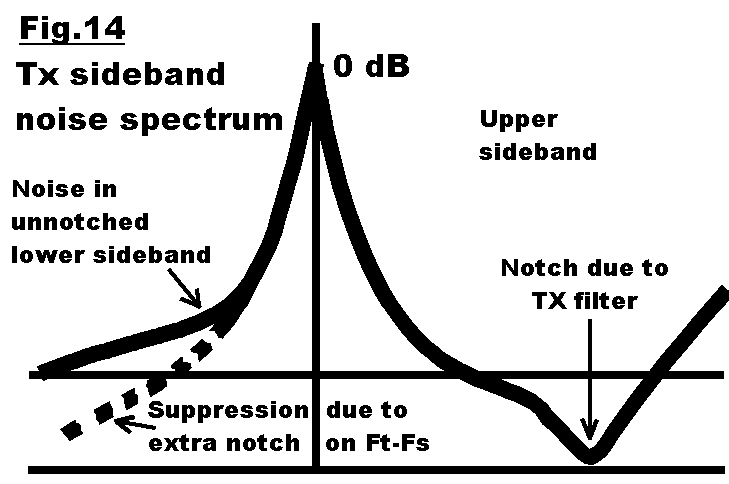
a. The noise energy on the non-suppressed lower transmittersideband frequency: Ft-Fs
b. The second harmonic of the transmitter carrier frequency: 2 x Ft
By reducing either one a better result can be achieved.
Typical levels.
| 1. | Noiselevel in lower sideband (see fig.1): | -70 to - 80 dB |
| 2. | 2nd harmonic of transmitter carrier: | fi. -80 tot -90 dB |
| 3. | Mixing losses in the intermodulating part: | fi. 30 dB |
| 4. | Resulting intermod signal level: | -120 to -130 dB. |
Intermod level is 20 to 30 dB above the receiver noise level. In this case, the receiver sensitivity can degrade 30dB (5 S-points!).
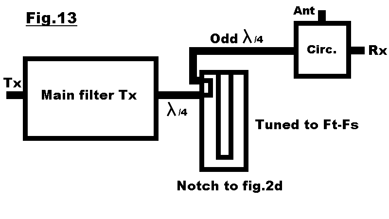
Most effective showed an extra notch on the non-suppressed under sideband (ft-fs). A sharp bandpass filter helps, but can shown to be not effective enough.
Adding an extra notch on the mirror frequency (70 cm).
|
|
|
|