|
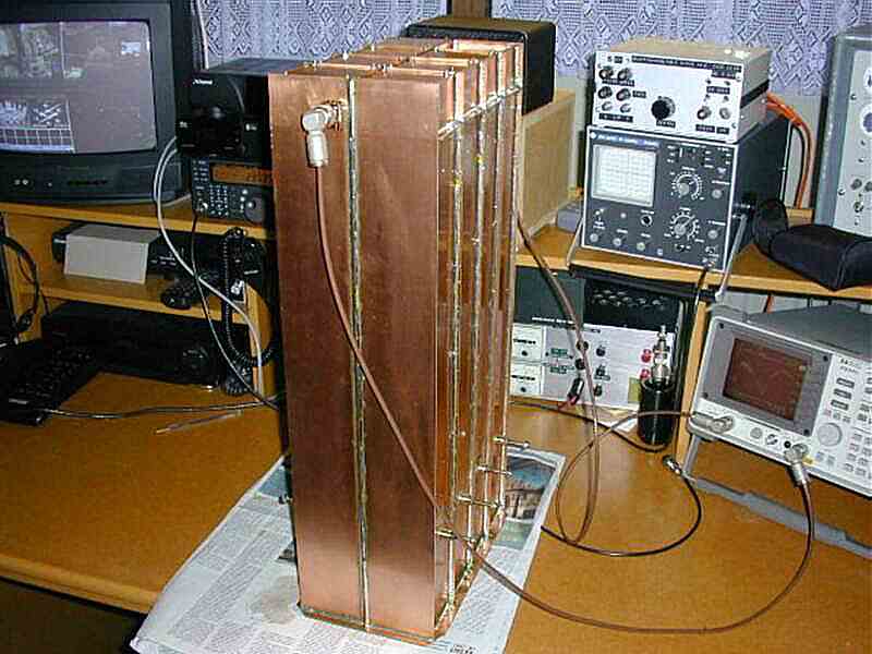
Some photos of the Pa0nhc 2mtrs duplexfilter. 00 10 14 |
April 2000 the PI3RTD duplexfilter was equipped with new (N) recepticles, as they are more relyable then BNC's. Edwin PA3GVQ, who workes with Libertel, borrowed measuring equipment (HP spectrum analyser). After re-adjustment the filter was measured. Finetuning is performed with the tuning-bolts on the side of the filter.
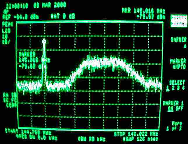
On the screen of the analyser the TX-part frequency characteristic is visible.
Below a sweep from the spectrum of the build-in signal generator feeding the TX-filterpart at the RX-frequency. An isolation of over 100dB is visible (top of screen = -90dBc, 10dB/div.). The noisy mountain on the right is the non-suppressed sideband noise of the signal generator around TX fequency. Peak level abt. -115dBc. Hor: abt. 125kHz/div.
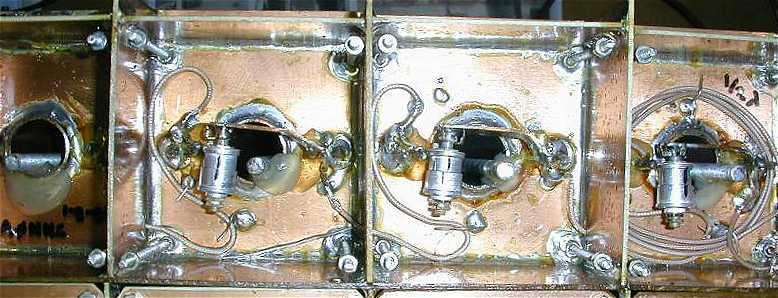
The picture below shows the top compartments of the TX-filterpart. On the left the TX bandpass cavity is visible (without parallel-C).
At the ends of the interconnectong coaxes the breading is soldered directly to the mass-sides of the coupling links. The unscreened coax centres then run as short as possible to the hot side of the coupling links.
As the airtrimmer-Cs are to short to connect directly between the hot sides of the copuling links, a wide strip of thick copper is used. The notchdeepness depends on it (see also last picture).
The steel rods are for course-tuning (performed only once). After adjustment they are "locked" using thermal glue.
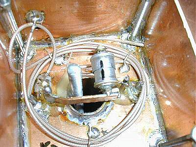
Here the last (notch-)cavity in the TX chain is shown in detail.
The outputlink on the left is connected to the antenna connector in the neighbouring compartment on the top. The ELECTRICAL length of this 50 ohms 1/2 wave PTFE coax cable is critical! The breading is soldered to both sides of the screening wall to prevent HF running over the outside of the coax.
The input coupling link on the right is connected to the outputlink of the former notch-cavity. The insulated 1/4 wave interconnecting 50 ohms PTFE coax cable runs through the screening on the right hand side. Observe the solderingpoints of the screening to mass near the couplinglinks.