 Why perfect impedance-symmetry is needed.
|
Testing and adjusting method for best balancing effect of active microphone output circuits. |
This measuring method is valid for all types of microphones connected to a mixer through a balanced microphone cable.
Why perfect impedance-symmetry is needed.
Hum or noises can occur from magnetic and static fields near microphone cables, or from the phantom power supply electronics. When hum or noise is injected in the balanced microphone cable signal wires on XLR pins 2 and 3, this will occur on both signal wires exactly in phase and with equal strength, but only if the total impedances on both lines are exactly equal over a very wide frequency range. The nearly perfect symmetrical microphone input circuit of a mixer then can cancel out these equally phased and strengthened hum and noise signals to a level up to 1000 times weaker.
But: good balance only can be achieved if the output impedance of the microphone on both signal pins 2 and 3 is exactly equal over a very wide frequency range (50Hz-50kHz).
Good cables and mixer input circuitry already are very well balanced.
In practice, the equal ness of the output impedances of both XLR pins 2 and 3 will decide, how good the noise canceling on the microphone line is.
Testing and optimizing the balancing effect:
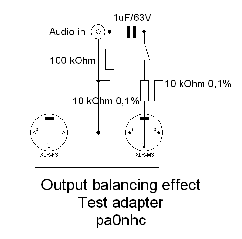
1. First make a test piece consisting of interconnected XLR male and XLR female plugs.
An audio-tone generator is connected via one capacitor of 1uF, and then separately onto XLR pins 2 and 3 via two carefully paired resistors of 1000 ohms to 10.000
ohms each (maximal 0,1% mismatch, measured using a digital ohm meter).
For easy result-checking the resistor on XLR pin3 can be disconnected by means of a switch.
2. Be carefull not to damage your ears by loud switching noises and test tones !!
- Turn off power of the mixer.
- Turn down the headphone volume (mind your ears!).
- Connect the headphone.
- Channel gain at minimum.
- Channel level at maximum.
- Channel EQ at neutral.
- Main slider at 0dB.
- Connect the microphone onto the mixer via the test piece.
- Connect the sinus-tone generator to the test-piece and adjust it for an output of 1Vrms @ 1500Hz.
3. Switch on the mixer. Wait one minute for stabilization of all voltages.
4. Open the switch on the test piece. The resulting tone on the VU meter is maximal loud as the output imbalance is now maximal.
4. Adjust channel gain until the red channel-LED just starts to glow. The cannel may not be overloaded.
5. Adjust the Main slider until the VU meters just read maximal (+10dB).
6. Close the switch on the test piece. De VU-meter reading will be lower. The difference is a measure of output balancing effect. The difference
should be greater than 30dB.
50dB is possible when carefully selected components are used.
7. Then check the balancing effect at 50Hz. This is the frequency of induced mains-hum. It should be better than 30dB.
8. Repeat at 5kHz and 50kHz (read the VU-meters). This are frequencies of injected mains spikes, which are causing random ticking noises. It should be better than 30dB.
Improving the balancing effect of an active microphone circuit:
The following is valid for some microphones with so called "transformerless outputs" (MCA SP-1. MXL990, Behringer C2 etc.):
9. In the microphone output circuitry:
Between XLR pin 3 and the emitter connection of a transistor, you can find a series resistor.
(*) In the old type Behringer C2 this resistor is completely absent, the connecting PCB-track on XLR pin3 must be opened.
10. Replace this resistor by a test-trim-resistor (potentiometer) of 100 or 470 ohms.
11. Use a test frequency of 500Hz (sine-tone).
Adjust the test-trim-pot for minimum VU meter reading (better than 40dB down).
12. Measure the value of the test trim pot carefully using a digital ohmmeter.
Replace the trim pot by a combination of fixed resistors with in total exactly the same value like the adjusted trimpot. Only 1 ohm difference to the value of the
trim pot can already means that only 30dB suppression can be achieved.
13. Test the balancing effect at 50Hz. If imbalance on 50Hz remains poor:
Replace the coupling condenser (s) between the FET and the base of the output transistor (s) (0,1 - 0,33 uF) both by 10uF electrolytic (not tantalum) capacitors (+
wire connected to the base of the output transistors).
14. Test the balancing effect at 5kHz. If imbalance on 5kHz or 50kHz remains poor:
In the microphone, replace both decoupling capacitors between XLR pins 2 and 1 and 3 and 1 by capacitors of the dame value but EXACTLY MATCHED (difference less
than 0,5%) . Use FOIL types for best performance (these have low temp. coeff.)
Succes, Nico.