|
Mix #31 material : |
|
|
| << |
(Copyright)
The use, copy and modification of
all
info on this site is only permitted for
non-commercial
purposes
and thereby explicitly
mentioning my radio amateur call sign
"PA0NHC" as the original writer / designer / photographer /
publisher.
|
FIRST press F5.
|
Mix #31 material : |
|
|
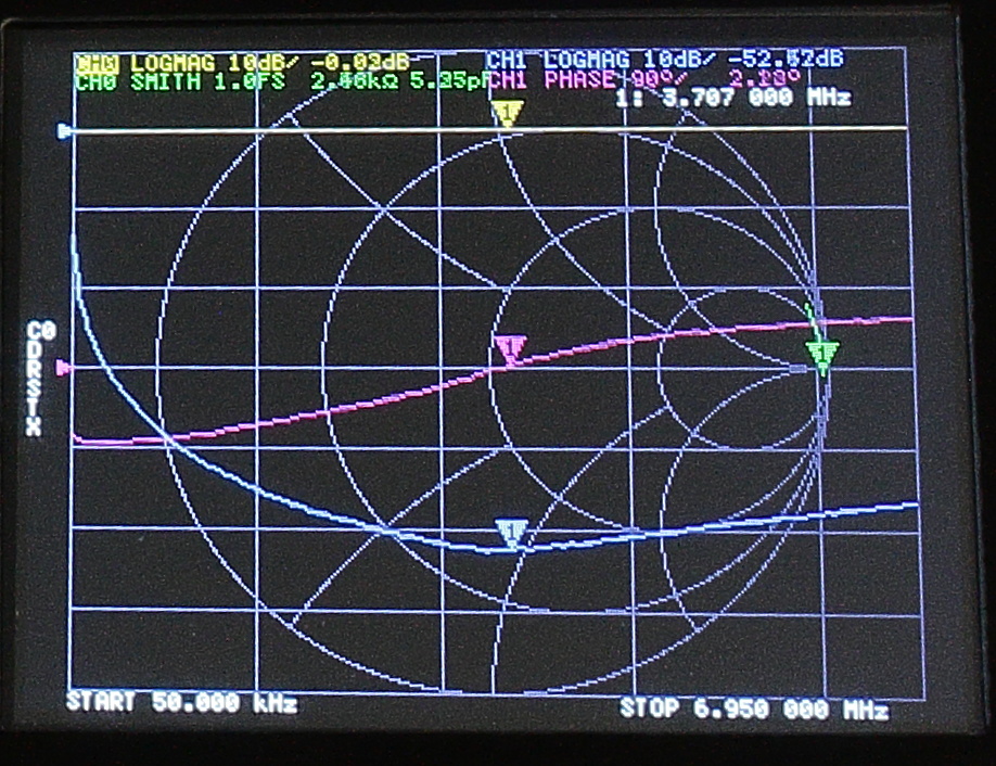
In the right hand picture, the green line in the Smith Chart stays very close to the Xaxis. Which means that the impedance is dominantly resistive, and becomes purely resistive at the 3.7 MHz marker.
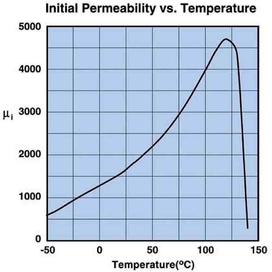
When the temperature of a mix31 core rises, the initial
Permeability (U's) rises too.
Then causing a CMC inductance to rise, and the CMC
resonance frequency to shift down.
As the core losses are not only temperature dependant, but also frequency dependant,
this should be given in a bundle of characteristics.
The FairRite catalog gives no such data.
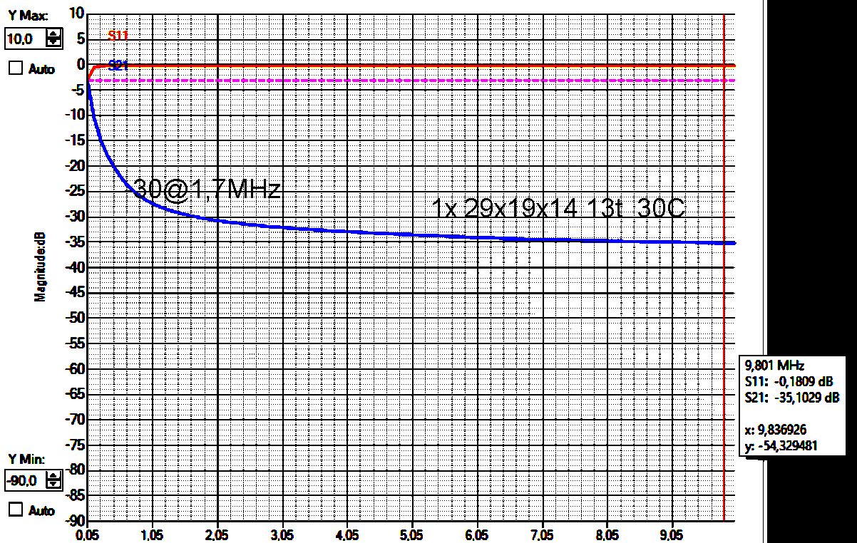 1 core with 13 turns RG316 PTFE coax. @30C |
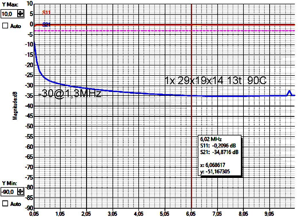 1 core with 13 turns RG316 PTFE coax. @90C |
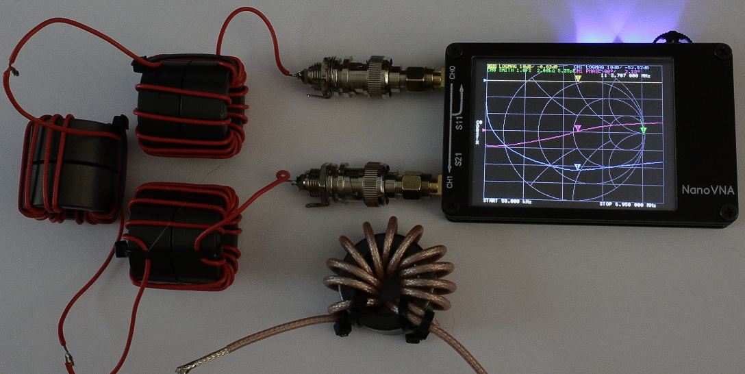
Frequency characteristics of a
CMC, made from one 29x19x14mm #31 mix ferrite core, with 13 turns RG316 coax.
Temperature rise has nearly no practical influence on these coil its
properties.
To get an indication of the impedance behavior when the core temperature changes, i tested a CMC by heathing it with a hairdryer, and measuring its temperature with an infrared thermometer.
When the CMC temperature rises from 30C to 90C, the frequency of maximal impedance shifts down from ca.10 MHz to ca.7.2 MHz, or by a factor 1.4. But as the impedance characteristic is flat, the attenuation changes very little between 1.8 MHz and 7.2 MHz when shifting to the left.
|
Conclusion : |
Application in the pa0nhc Cobra Antenna : |