| A single resonator helix band pass filter for the two meter band, using wire coupling for better suppression of
FM-broadcast and TV band1 signals. pa0nhc, 2002 07 18. / 20110307 |
|
| Fig. 1
|
|
| Fig. 2 |
Properties
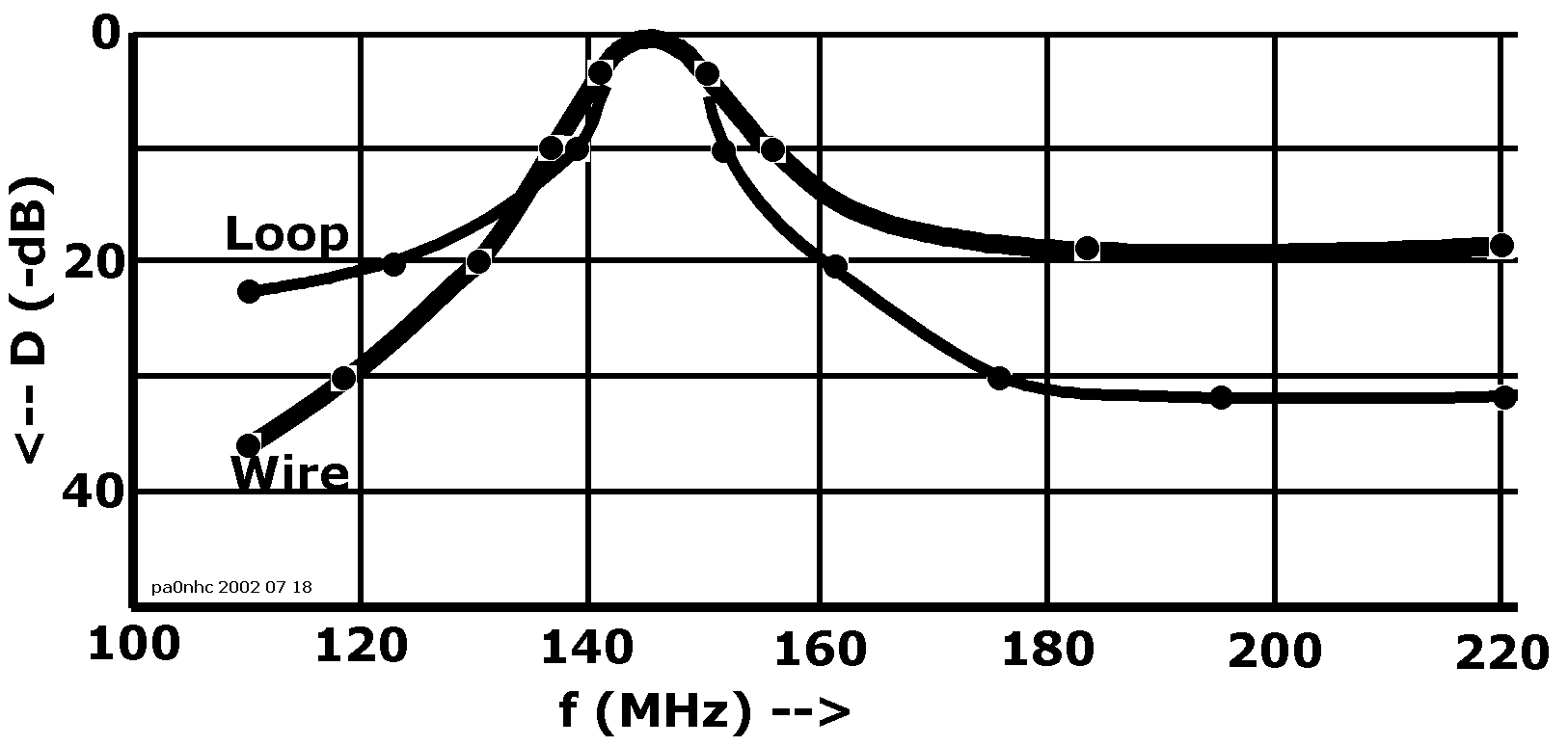
This construction can be of an advantage in those cases, where optimum selectivity on the low side of the resonance frequency
is most important.
For instance, if a strong FM-broadcast signal has to be suppressed.
Here we have no coupling loop at the out-going port, but a piece of wire, running in parallel under the coil winding, at a few millimeters distance. From the frequency characteristic of fig. 1 can be concluded, that this results in a far better selectivity below the resonance frequency.
The wire seems to act like a capacitive coupling, with the stray-capacitance between the coil and the wire acting as the coupling-C. Together with the following to mass connected self inductance of the wire, this results in an extra high-pass-filter, connected in series with the output-coupling.
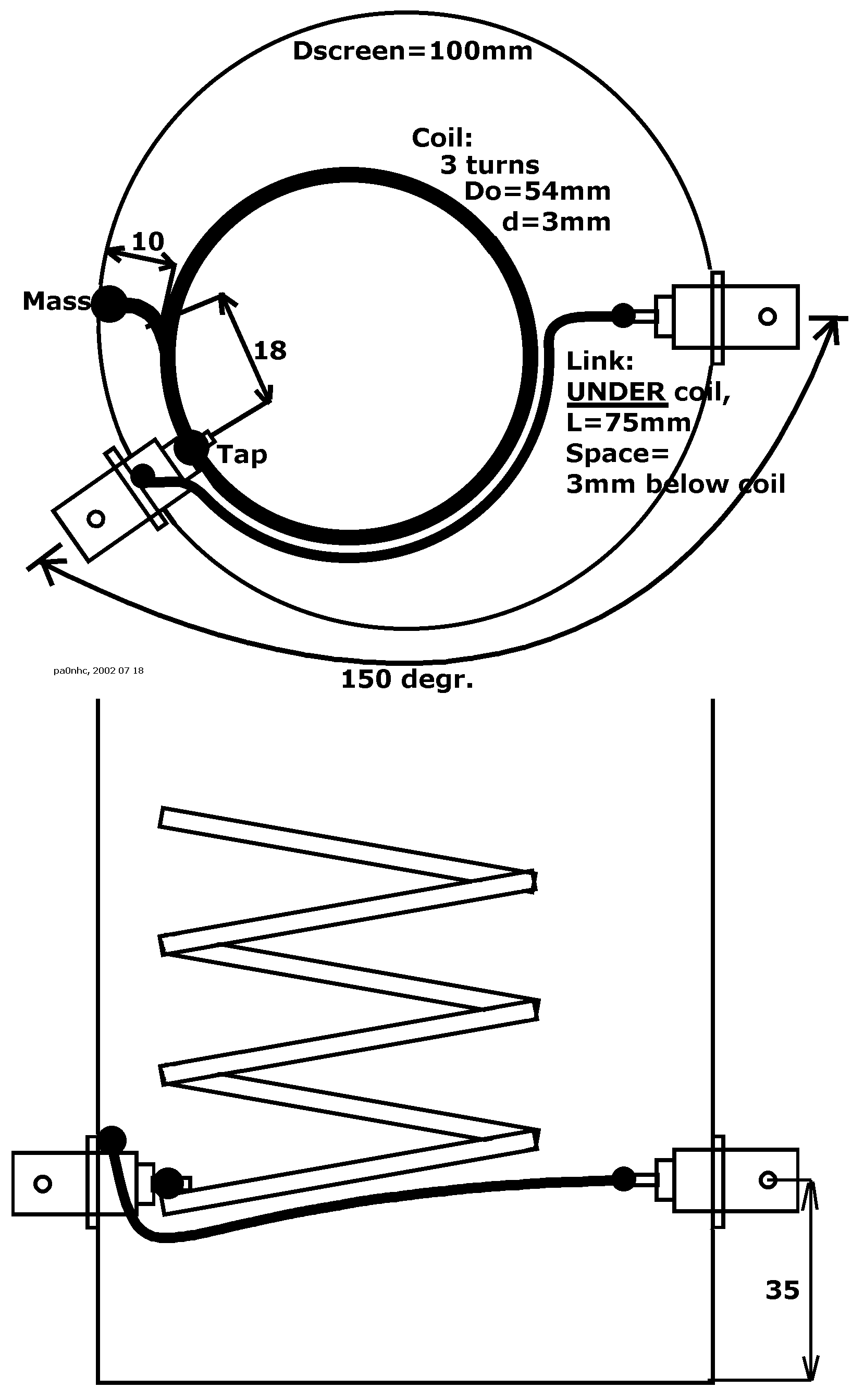
Construction
Place the in- and output-BNC's in an angle of 150 degr. This makes a coupling wire of abt. 75mm length possible.
The coupling wire runs from the mass-side of the input-BNC, to the central pin of the output-BNC.
Bend this wire with the same radius as the coil.
Bend the connection leg to the output-BNC at 90 degr. See fig2.
In fig. 2 the coupling wire is for clarity drawn beside the coil, but the coupling wire has to run exactly in parallel UNDER the coil.
Solder the coil UNDER the input-BNC-pin, with the coil its mass connection to the screening, in such a way that the "Tap" is 18 mm long.
Adjustment
The output coupling is adjusted by varying the distance between the wire and the UNDERSIDE of the coil. Adjust this distance for equal
maximal input- and output-reflection-damping of at least 20dB. This maximum is at the resonance frequency of the coil. Adjust the resonance frequency by cutting the coil top, and
bending the last cm of it.
If the reflection damping cannot be made optimal, the input coupling is not good. It must be changed, by unsoldering the coil and replace it so, that the "Tap" becomes a bit shorter or longer.
Always measure the selectivity at 120 MHz and 170 MHz. If the selectivity is OK, but reflection damping or insertion loss is not, the "Tap" must be made a bit longer. If reflection damping is OK, but the selectivity is not, the "Tap" must be made a bit shorter.