| << |
Optimal 160m and 80m
versions. Mono or dual
band. 20201107
(C)
The use, publication, copy and modification of all info on this site is
only permitted for non-commercial
purposes, and thereby explicitly
mentioning my radio amateur call sign "PA0NHC", as the original
writer / designer / photographer / publisher. (C)
|
 Ideas for an optimal loop construction for 160m and 80m.
Here ideas for constructing a 6.4 m diameter low loss 160m + 80m circular loop with two pieces
9.5
meters long 39 mm
diameter Cellflex
LCF114-50.
REM : the coax cable impedance is not important, the diameter of the screening is,
as coax end connections then can be closed using 42mm copper water pipe end caps.
See the possibility to use a 6.5
meter long metal mast.
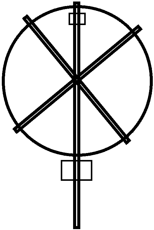
A
6.5 m long mast with a "X" shaped supporting cross ( 4x 3.5 m long pieces
of wood) can be used to install
the
loop. The angle between both "X " parts should be 60 degrees for
optimal stiffness of the loop.
The free space between the lowest point of the loop and the ground level is 1.5m. If
the mast can be turned, the loop could be directed to suppress low angle noise
sources.
Somewhat
simpler but less stiff is the use of one horizontal supporting bar as used in my
present smaller loop.
Guy wires at the ends of the horizontal bar can prevent torque onto the antenna during
stormy weather.
The
match box will be installed under and connected to the open loop top.
The tuning box will be installed under and connected to the open loop bottom.
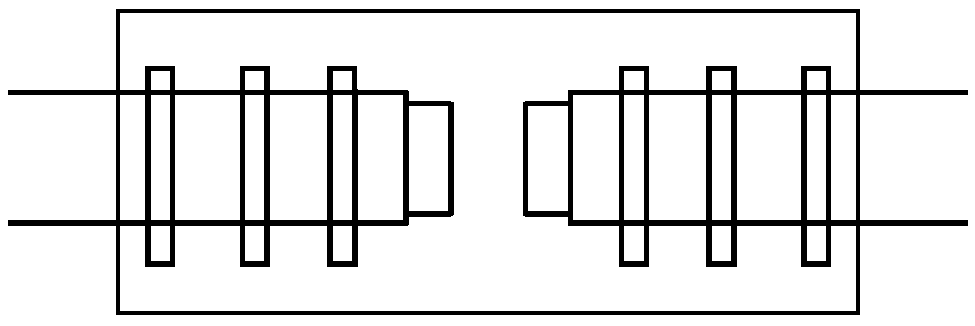
Waterproofing and connecting the coax ends.
 - Brass or copper water pipe end caps with an internal diameter of 35mm
or 36mm can be used.
- Brass or copper water pipe end caps with an internal diameter of 35mm
or 36mm can be used.
- Remove 2 cm outer insulation from all coax ends.
- Drill 4.8 mm holes in the center of the end caps.
- Tap the holes M6.
- Screw M6 screws from the cap insides, to the cap
outsides.
- Solder the screw heads to the inside of the caps.
- Bend the coax screenings a bit outwards, to come in
contact with the flanges of the end caps.
- Pre-tin the rims of the end caps, and the ends of the
coax screenings.
- Shift the caps over the coax foam insulations.
- Solder the end caps to the coax screenings.
- Wind vulcanizing butyl tape over the gap between coax outer insulations and
the end caps.
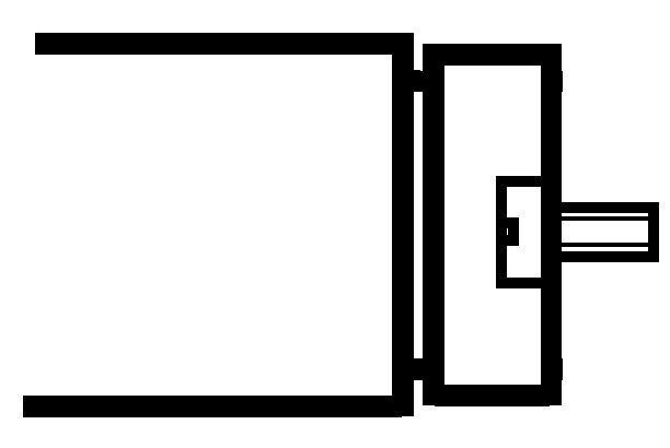
 - Mount
two coax ends onto a thick (10mm) Trespa (or
Plexyglas) feed point plate. See sketch
===>
- Mount
two coax ends onto a thick (10mm) Trespa (or
Plexyglas) feed point plate. See sketch
===>
- Use stainless steel clamps (made from 6mm treaded stainless steel rod,
nuts and rings).
- Clamp firmly, but try not to damage the coax outer insulation.
- Water
protect these places (for instance with two layers transparent metal paint).
- Connect the wires for the tune box to their M6 screws.
Use two nuts per connection.
- Spray the unprotected parts of these connections with two layers of
transparent metal paint.
IMPORTANT
:
The length and copper diameter of the loop connecting wires are of influence to the
calibrated values of the series resonance capacitors.
These capacitor values should be determined including a pair of connecting wires,
with the same copper diameter and length as those of the wires which
actually will be installed between the match box and the loop.
Fixing the loop to the supporting X cross :
As coax has an outer insulation :
- It needs not to be painted, and
- Can be fixed
onto a supporting "X" cross without insulation.
- Use home made
stainless steel clamps or use
- Pairs of "X" crossing strong black "tie
wraps", which must have a stainless steel locking tooth.
At the
lower open loop end :
Water tight and
dependable connections to the tuning box can easily be made by :
- Installing two female N-busses onto a non-metallic (ABS) tune box.
- Installing onto each of two pieces RG214 coaxes, one male N connector, and
- Remove some inner insulation at the other coax ends,
- Flatten these screening ends, and pierce a 6mm hole.
- Connect these screening ends with rings and two nuts to the M6 screws at
the lower antenna coax ends.
- Waterproof these connections with :
- Crimp hose and
- Two layers of transparent lacquer.
Tuning capacitances.
Loop :
Circular, circumference 19 m,
36mm radiator.
Loop inductance and tuning capacitances were calculated with "LoopCalc".
REM : do NOT believe with the LoopCalc computed I, Z,B,Q,E and loss
figures.
These are completely WRONG for this relative LARGE loop. Reported values are far to HIGH.
Cause : the RFcurrent around this relatively
LARGE loop circumference is NOT constant.
It VARIES, and is on the tuning capacitor for instance 50% smaller than in
the feed point.
This loop performs in real life much better than suggested.
Its
bandwidth in the 160m band should just be useable for SSB.
Calculated loop
inductance : 32.3 uH.
Calculated tuning capacitances :
1.8 - 2.0 MHz : 332 - 269 pF. Variation 63 pF. Tuning ratio 3.2 kHz
/ pF.
3.5 - 3.8 MHz : 88 - 74 pF. Variation 14 pF.
Tuning ratio 21.4 kHz / pF.
At 80m tuning is critical due to the
high ratio kHz/pF.
The DC tuning motor must be able to start positively while turning VERY slow.
In slow mode driven by very short strong DC pulses 2x per second.
Tuning capacitor
voltage calculations :
Based on measured feed point impedances, calculated tuning capacitances and
loop currents :
2.0 MHz / 100W power : 2.57 kVrms / 3.6 kVp
3.8 MHz / 400W power : 3.25 kVrms / 4.6 kVp.
Transformer
TR1
TR1 can be constructed the
same way as for the 80/40m version :
80 m = 9 turns : 3 turns.
160 m = 9 turns : 1 turn.
The inductance and parallel impedance of TR1 could be
optimized for 160m :
- By gluing two 61mm #31 cores on top of each other, and
- Winding the same number of turns.
With the transformer then wound onto two stacked cores, the leakage inductance will
become higher.
The values of the needed series tune capacitors will become
smaller.
The values of
the series capacitors must now be determined by measuring,
wile connected to :
- a 5.6
Ohms low inductance RF power resistor for 80m, and
- a 0.6 Ohms low inductance RF power resistor for 160m.
This
is not tested here.
Mono band versions.
Circular loop, 39
mm Cellflex
LCF114-50, circumference 19 m.
Transformer :
For 80m, the transformer
TR1 should be 9 : 3 turns on one, or two stecked 61mm #61 cores.
For 160m, the transformer
TR1 should be 9 : 1 turns on TWO stacked 61mm #61 cores.
The value of the series capacitors must be determined by
measuring like above.
The
relay can be bypassed.
A
continues activated 5W anti-condensation heating is always recommended.