|
The PA0NHC low budget easy homemade and adjusted 8 cavity 2m repeater duplexfilter. |
|
The PA0NHC low budget easy homemade and adjusted 8 cavity 2m repeater duplexfilter. |
I am the builder of the two regional amateurrepeaters (2m PI3RTD / 70cm PI2RTD) in Rotterdam. A repeater working on one antenna needs a duplexfilter. When planning the construction of the station, a professional duplexfilter for the 2mtrs releay was out of reach, as nearly no budget was avalable. So one had to be build. After study of all avalable information, some experimental cavities were made. This deepened the knowledge, but also awakened more questions, which were answered after more experiments. In order to fullfill all demands, i desided to devellop a duplexfilter my self. I build it, and it works stable for years now. Every HAM with enough building experience can build and adjust it too. Cheaply!
Facts and questions about some duplexfilter-constructions.
Diplexer
is a coupler for two different frequency bands (f.i. 2mtrs and 70cms). Frequency difference is
big, f.i. 300%. Decoupling of 60dB is good. Diplexers combine low- and high pass,
or pieces of coax cable and simple series resonating tuned circuits. They are
relatively simple in comstruction and small in size, and contain small coils and
small C's. Decoupling is typically between 30dB and 60dB. Due to the large
frequency-separation, the tuned circuits in the connected transceivers deliver
enough extra selectivity
Duplexer
couples a transmitter and a receiver which are
simultaniously working on the same frequencyband, and operating with
very little frequency difference (f.i. only 0.37%).
They need very high-Q circuits. These filters are therfore allways big and critical
in construction and adjustment, and consist of coaxial resonators.
Decoupling of 90dB or more can be acheeved.
Why a duplexer.
A duplexfilter is neccesary, in order to connect a repeatertransmitter
and -receiver on the same antenna during "full-duplex" operation. What
the receiver is hearing, the transmitter sends at the same time through the same
antenna at the same frequency-band, at a very small frequency difference.
Professional duplexfilters are expensive, and sometimes not good enough for the high-demanding amateur-service.
Homeconstruction is often relatively expensive and difficult, due to the use of thick copper or brass pipe and plate, silverplating, the need of machining it on a lathe, and the use of tracking-generator and spectrumanalyser for adjustment.
In amateurliterature i found a few descriptions for construction of duplexfilters from copperpipe, aluminium sheet or copperclad. I studied a few of these designes, and did build a few testcavities. But i found the descriptions incomplete, the construction expensive or difficult, or the construction mechanically instable. After the first experiments a lot of questions arose:
Therefore i made a full 1/4 wavelength cavity, to test my own construction idees. During experiments the nessesary constructiondetails were devellopped, with in the back of my mind:
KISS (Keep It Stupid Simple).
The resulting construction could be the answer for those amateurs, who cant buy a professional duplexfilter, but still want a very good seperation between transmitter and receiver for their repeater operating on ONE antenna!
Configuration:
The two extra cavities attenuate very strong, in-band and near-band signals to aviod:
Properties:
Pre- and final adjustments possible with:
Adjustments:
Specifications:
![]()
Frequency characteristcs.
The performance is plotted on the safe side. Lateron, measured with professional equipment, the notch-deepnes showed to be better then -100dB.
Narrow-band performance
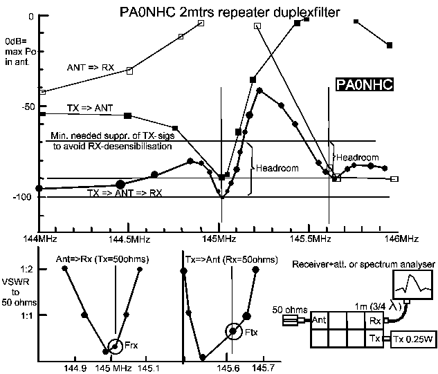
This graph shows, that the transmitternoise in the upper
sideband is reduced abt 15dB, thanks to the use of a bandpass cavity in the
transmitter chain. This can enhance practical receiver-sensitivity.
Wide-band performance
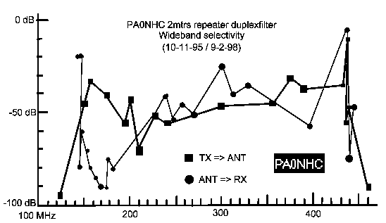
From the lower graph can be seen, that the extra bandpass cavities result in suppression of out-band signals of more then 30dB at most frequencies, and on the second harmonic of the transmitter. This prevents intermod and backdoor mod. by strong signals from fi. peager networks and broadcast transmitters.
The selectivity of the duplexer is far better then a lossy receiver-inputfilter. A simple low loss input network in the first stage of the receiver for a good match to the 50 ohm source is adequate and optimal. That way it is possible to enhance the practical receiver sensitivity, while keeping good high-level properties of the first receiver stage.
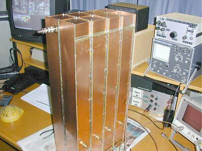
<<-= Some photos and
measuring results.