|
|
|
| << |
Nagloop tester : Magnetic field strength indicator. 20170715 / 20171221 / 20230322 |
(C) The use, copy and modification of all info on this whole site is only permitted for non-commercial purposes, and thereby explicitly mentioning my radio amateur call sign "PA0NHC" as the original writer / designer / photographer / publisher.
|
|
|
Properties.
This
broad band system gives an indication of the
magnetic
near
field strength
of a
short wave
"Magnetic
loop"
antenna.
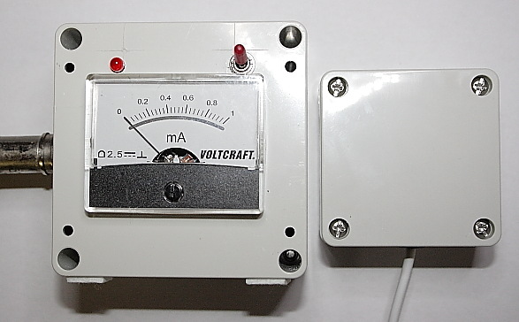
The
little sensor unit of it is installed outside, near a loop antenna. Its input is
protected against over voltage.
The relative field strength is read at the transmitter site with a meter unit, connected
to the sensor through a twisted 3-wire cable.
The sensitivity of the system is switch able between LOW and 20dB
more sensitivity, enabling testing with 100W, and less annoying low power.
Power source is a 4.5V from a three AA alkaline battery pack. Total supply current is 2
- 8 mA. Very long
battery life can be expected.
Testing the
finished indicator, using a dip meter as RF source.
Connect the sensor unit to the indicator unit. Switch the indicator unit to
sensitive.
Hold the coil of a dip meter in line with the sensor ferrite rod,
close
to the grounded end of the ferrite coil.
Set the dip meter signal strength to
maximum. Change the dip meter frequency over the whole short wave range
and observe the indicator
meterdeflection. Using a Heathkit HD-1250 dip meter, a good meterdeflection was
observed between 1.5MHz and 70MHz .
 Testing your magnetic
loopantenna.
Testing your magnetic
loopantenna.
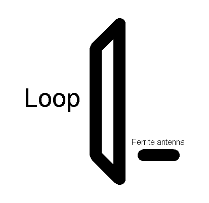
See the drawing at the right for a possible orientation of the ferrite sensor
coil, in respect to
the orientation of the loop antenna. In order to minimize RF induction
onto the signal cable and obtaining best indications, the 3-wire twisted
connecting cable cable should run at 90 degr. angles away from
both :
a. the ferrite rod in the sensor unit
and
b. the lowest part of the Magnetic loop antenna.
-
Start with
the sensor unit near the center of the lowest conductor of the loop,
- and
change the distance in respect to this conductor.
-
Keep the sensors ferrite rod at 90 degr. in respect to the loop surface.
You have to experiment with the location of the sensor unit (closer / further / higher / lower).
With S2
on the indicator unit in its UNsensitive position,
and with 100W transmitter power applied to a correctly tuned loop antenna, you
should then get nearly full meter scale deflection.
With S2 on the indicator unit in its MOST sensitive position,
you can test with low transmitter power, causing as little as possible
interference on the communication channal.