|
New PCB. Use ONLY the specified ferrite cores ! Cabinet : Hammond 1555VZGY |
 |
| << |
Parts list for
matching system |
|
New PCB. Use ONLY the specified ferrite cores ! Cabinet : Hammond 1555VZGY |
|
|
v. 20200606 |
Order Nrs |
|
| Box | Hammond 1555VZGY UV proof splash watertight. | 1977734 |
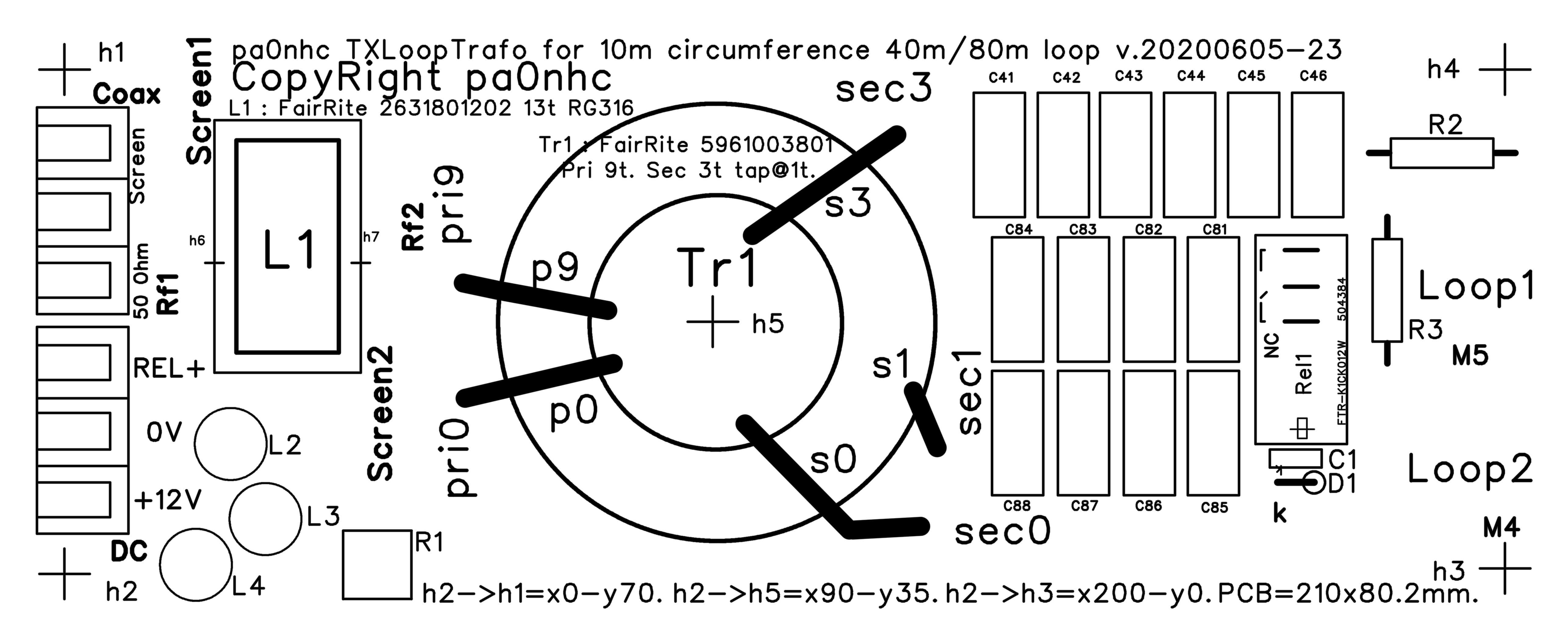
| PCB | pa0nhc PCB 20200605-23 | pa0nhc@gmail.com |
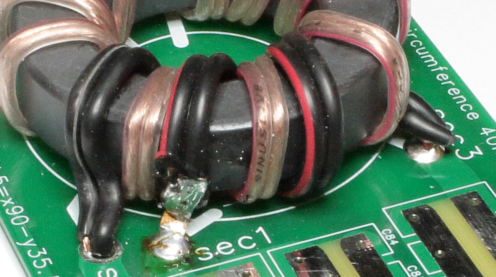
| Tr1 | RF magnetic RFpower transformer.
See
construction. Updated 20221204 61mm mix
#61 ferrite ring core : Fair-Rite 5961003801 .
or FT240-61. If no PTFE wire is avaialable, you
can use easier to handle : |
Mouser.com
|
| L1 | Common Mode Choke
(balun). See construction. Wind 13 turns thin coax neatly in the hole beside each other. Fixate winding ends to the core, and the CMC to the PCB, with small black ty-wraps. Ferrite ring core
==>> Fair-Rite 2631801202
(28/19/14mm) ==>>
MIX #31 <<== DO NOT use any other ferrite mix ! 2 m Coax RG316 (or RG174) suitable up to 400W. |
Arrow.com Mouser.com dx-wire.com
602710 |
| L2,3,4 | Fastron 09P220k-51 . RF chokes, d=9, RM5. Imax >= 330 mA, Fsr >= 10 MHz. | 440433 |
| Rel1 | Fujitsu FTR-K1CK012W. 440V~ / 16A. 12V mains voltage relay (high voltage / current). |
504384 |
| R1 | 56 ohm 5W wire wound resistor (anti condensation heather). | 401986 |
| R2,3 | 10k 1W or 2W metal film resistor (static charge bleeders). | 419567 |
| "50 Ohm" "Rel+" |
Degson DG950-9.5-03P-14-00AH fits the PCB. Screw terminals 5.3 mm2. RM9,5. | 1327229 |
| 4x water tight cord
grips for RG400 coax, 5,3mm relay line, and 2x 3,7mm loop connection
twin DC line. For RG58 feeder, relay cable and antenna connection wires, use : "2,5 - 6,5 mm" size. For thicker coax feeder use bigger 7-12mm size. Install with some Vaseline (petroleum gelly) to make them water tight. |
Aliexpress.com
(Conrad). |
|
| C1 | Capacitor 100n 50V RM5 | 531855 |
| C40-46 | Total value abt. 890 pF. 8x100p Wima FKP2 630V + 1x180pF 630V film or 1kV NP0 OR 500V Mica. MEASURE resonance as being 7100 kHz. | |
| C80-88 | Total value abt. 6400pF, 8x680pF Wima FKP2 630V + 1x 270pF 630V film OR 500V Mica. MEASURE resonance as being 3650 kHz. | |
| Series tuning capacitors | Use as much as possible capacitors in parallel. For
instance :
IMPORTANT : For measuring C40 and C80 with NanoVNA
V2Plus4, use low inductance resistors as dummy loads : |
Wima, FairRite : Mouser.com.
Silver mica : |
| D1 | Diode 1N4001 | 564843 |
| 2x | Solder able brass or copper screw M5x10. (Must be inserted from, and soldered onto the bottom side of the PCB). | |
| 4x | Solder able brass or copper nut M5 | |
| 5x 15x |
Stainless steel screws
M4x30 (for
fixing the PCB into the box) Stainless steel (lock) nuts M4. REM : the PCB MUST be mounted at leas 15 mm above the box bottom. METAL nearer than 15mm to the Tr1 ring core can noticeable lowers its Ui value !!! and the resonance frequencies of the transformer circuit. |
|
| 2x | Connector strips each : DG950-9,5-03P | 1327229 |
| Tune capacitor in tune box. |
2x 600pF 2kV. (2x600pF in series and balanced => 4kV.) http://www.elektrodump.nl/nl/48-draaicondensator Art.1776 |
elektrodump.nl Art.1776 |